
Fanuc Spindle NVRAM Initialization Procedure
| PROCEDURE 1 NVRAM INSTALLATION AND INITIALIZATION INSTRUCTIONS |
GENERAL INFORMATION:
The Spindle PCB on Digital Spindle Drives uses a non-volatile memory chip (NVRAM) which contains data from the spindle EPROM chips and also the Machine Tool Builder's spindle parameters
PROBLEM:
An incomplete temporary power down of the AC Spindle Drive can allow the CPU to write incorrect data to the NVRAM chip. If this corruption of the data occurs, Alarm 17 (AL-17) will result on the Spindle PCB 7-segment display upon power up. The NVRAM chip must be initialized to restore operation
AFFECTED DRIVE BOARDS:
The following table identifies Spindle PCBs with which this problem may occur.
| APPLICABLE SPINDLE PRINTED CIRCUIT BOARDS | ||
| A16B-1100-0200 | Before 13B | Size 1S-3S Drive |
| A16B-1100-0261 | Before 08B | 3I and 6I Drive |
| A20B-1003-0300 | Before 07B | Size 8I Drive |
| A20B-1003-0010 | Before 10B | Size 6S-22S Drive |
| A20B-1001-0120 | Before 17F | Size 6-22 Drive |
SOLUTION:
For Spindle PCB's in the above list, an adapter PCB (A20B-9001-0030) is installed between the NVRAM chip and the Spindle PCB socket to prevent reoccurrence of AL-17.
See the INSTALLATION INSTRUCTIONS FOR SPINDLE ADAPTER SOCKET for the procedure to add this Adapter PCB.
MATERIALS REQUIRED
| A20B-9001-0030 | SPINDLE ADAPTER PCB |
| INSTALLATION INSTRUCTIONS FOR SPINDLE ADAPTER SOCKET |
- With power on, and no spindle alarms active, record the Spindle Parameters with the following method:
- Press all 4 buttons ("MODE", "UP", "DOWN", and "DATA SET") simultaneously until 7-segment display reads "FFFFF" and then release the keys.
- Press and hold the "MODE" button and use the "UP" and "DOWN" buttons to go to the different parameter locations and record the values for each parameter (1 - 40) on paper. These values will be set to default values when the unit is initialized.
- Remove power from the Spindle Drive.
- Remove the NVRAM chip from the socket located near the 7-segment display on the Spindle Drive PCB.
- Plug the Adapter PCB into the NVRAM socket on the Spindle PCB. Install the Adapter PCB so that the jumper is in the same direction as the IC chips on the Spindle Control PCB.
- Plug the NVRAM chip into the Adapter PCB with the orientation notch DOWNWARD.
- Put the Adapter PCB jumper to the SET position.
- Put the jumper (S1) on the Spindle Drive PCB to the TEST position.
- Power up the Spindle Drive. The 7-segment display will continually count up with hexadecimal numbers.
- Press all 4 buttons on the keypad simultaneously until the 7-segment display reads "FFFFF". Release the buttons. The display will resume counting hexadecimally.
- Press and hold the "MODE" button and press and release the "UP" button until the display reads "FC-22".
- Press and hold the "DATA SET" button until the display blinks on and off 3 times with the message "Good" displayed.
- Remove power from the Spindle Drive.
- Put the jumper (S1) on the Spindle Drive PCB back in the DRIVE position. (Leave the Adapter PCB jumper in the SET position).
- Power up the Spindle Drive.
- Press all 4 buttons on the keypad simultaneously until the 7-segment display reads "FFFFF". Release the buttons.
- Set the Spindle Parameters by holding the "MODE" button in and pressing the "UP" or "DOWN" buttons to get to the desires parameter location. See Note II.
- Set the MTB's parameter values by incrementing or decrementing the default parameter value with the "UP" or "DOWN" button.
- When all values have been set, push and hold the "DATA SET" button until the display reads "88888" and then release it.
- Move the Adapter PCB jumper to the Drive position. (This disables data from being written to the NVRAM chip.)
NOTES:
- If it is necessary to change any of the Spindle Parameters again, the Adapter PCB jumper must be put into the SET position. Follow the procedure in the Maintenance Manual for setting Spindle Parameters. Put the Adapter PCB jumper in the DRIVE position when complete.
EXAMPLE:
If a parameter is changed in accordance with the Maintenance Manual, without first putting the Adapter PCB into the SET position, the drive appears to successfully take the new parameter setting. When the Drive is powered down and back up again, the new parameter setting will be lost.
- Only set parameter values F-00 through F-40. Parameters F-41 through F-53 MUST REMAIN AT THE DEFAULT VALUE AFTER INITIALIZATION.
| PROCEDURE 2 SPINDLE DRIVE NVRAM INITIALIZATION |
Many Fanuc Spindle Drives share a common Control PCB. For all Digital; Spindle Drives (with the exception of Serial), information from a pair of EPROMs mounted on the Spindle Control PCB furnishes the Fanuc motor specific data required by the drive. Information from these EPROMs along with the MTB's parameter settings are maintained on the Spindle Control PCB in a non-volatile device called an NVRAM chip. When changing the Spindle Control PCB, it is important to initialize the NVRAM on the replacement Spindle PCB prior to setting the MTB's parameters.
NVRAM Initialization Procedure
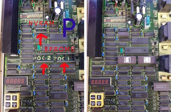
- With power off, move the
existing pair of EPROMs from the faulty Spindle Control PCB to
the replacement PCB.
Eproms are marked up with the version number
of software and below this 001 and 002, These numbers correspond
to the numbers on the PCB (see picture below). The Eprom will
have a notch in please align this with the notch in the IC
Socket on the Spindle Card.
The NVRAM IC will require swapping over from your old board. - With power off, move jumper S1 to the TEST position.
- Move jumper SH to the SET position (if your drive has this jumper).
- Turn power on. Simultaneously press all 4 keypad buttons momentarily and use the MODE and UP arrow keys to increment to FC-22 in the 7-segment display.
- Press and hold the DATA SET keypad button until "Good" appears on the display.
- With power off, move jumper S1 to the DRIVE position.
- Apply power and set the MTB's parameters with the procedure in the Maintenance Manual. Move jumper SH to the DRIVE position (if your drive has this jumper).
HINTS:
Record you MTB parameter settings BEFORE you have a drive problem.
Spindle Interface Software RevisionsAnalog Interface Spindle Software Series
Prior to GE Fanuc’s digital serial interface, analog interface digital spindle amplifiers used different PROMs, mounted on the amplifier, for each motor. These software series were as follows (as listed in the spindle maintenance manuals):
- 9700 series SW for the A06B-6055 series amplifiers
- 9800 series SW for the A06B-6059 S series amplifiers
- 9900 series SW for the A06B-6060 I series amplifiers
- 9B00 series SW added speed range switching for the S amplifiers
- 9C00 series SW added spindle motor switching for the S amplifiers
Serial Interface Spindle Software
Serial interface digital spindle amplifiers use common software for all motors as the motor type is defined by setting parameters in the CNC.
A number of serial interface spindle amplifier software versions have been developed. The function and latest revision of these versions are identified by the #H5XX amplifier order number suffix as indicated in the table below:
| Serial Interface Software Function and Revision by Amplifier Order Number | ||||
| Amp | Amp Suffix |
Software | Revision | Function |
| 6062 | #H500 | 9A00 | 1E | First serial amp worked with 16 bit Series 0 CNC |
| 6063 | #H510 | 9A10 | 1N | First serial amp for 32 bit CNCs |
| 6063 | #H511 | 9A11 | 1L | Adds spindle motor switching |
| 6063 | #H512 | 9A12 | 1D | Provides high speed operation |
| 6064 | #H520 | 9A20 | 1J | New standard, adds override feature |
| 6064 | #H521 | 9A21 | 1M | Adds spindle switching function |
| 6064 | #H522 | 9A22 | 1A | Provides high speed operation |
| 6064 | #H550 | 9A50 | 1W | New standard software for IGBT version amplifier |
| 9A52 | SPECIAL | |||